Selecting the right screw conveyor components begins with understanding the material, not simply choosing a larger motor. Powder, grain, sludge, and abrasive minerals behave differently inside the same trough. Their moisture, temperature, bulk density, and flow pattern can change performance quickly.
Dr. Andrew W. Jenike, a pioneer in bulk-solids engineering, stated, “The conveyor must be designed for the material, not merely for the capacity.” This principle remains practical today. A reliable screw conveyor usually combines flights, a shaft, troughing, inlet and discharge sections, hanger bearings, end bearings, seals, and a properly sized drive. Each part carries a different responsibility. Flights move the product. Bearings support rotation. Seals protect the process from leakage and contamination. Small details matter.
The top screw conveyor components are not always the most expensive ones. A poorly selected hanger bearing can create heat, noise, and unexpected downtime. An undersized seal may allow dust to escape around the shaft. A weak shaft can flex under a heavy, uneven load. These failures are rarely dramatic at first. They often begin with vibration, residue, or a strange smell near the drive.
Experience also exposes an uncomfortable truth: no component list guarantees success. Installation alignment, cleaning habits, inspection access, and operator training matter just as much. Even a well-engineered conveyor can perform poorly when assumptions remain untested. This guide examines the essential screw conveyor components, their functions, selection factors, and the practical mistakes that engineers and maintenance teams should reconsider.
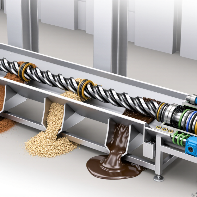
A screw conveyor moves bulk material through a rotating helical flight. Its main components must work as one system. The screw flight applies forward force inside a trough or tubular casing. The casing controls the material path and reduces spillage. In open designs, covers improve safety and limit contamination. Inlet and discharge openings determine how evenly material enters and leaves the conveyor.
The drive assembly includes a motor, gearbox, coupling, and drive shaft. It controls torque and rotational speed. A slow speed may protect fragile material, while higher speed can increase capacity. End bearings support the rotating shaft at both ends. Longer conveyors usually need hanger bearings between sections. These supports prevent shaft deflection, but they can disturb material flow. That trade-off deserves careful attention.
Seals protect bearings from dust and moisture. Wear-resistant flight edges can extend service life when abrasive material is handled. Adjustable supports help maintain alignment on uneven floors. Guards should cover exposed rotating parts. Practical inspections often find loose bolts, worn seals, buildup near the inlet, or unusual vibration. Small signs matter. Even a well-designed conveyor can perform poorly after installation. Misalignment, overloading, or poor cleaning access may create problems that calculations did not predict. Regular checks should compare operating noise, current draw, material flow, and bearing temperature.
The chart presents representative dimensional ranges commonly used when sizing major screw conveyor components. Actual values depend on material, capacity, speed, conveyor length, and operating conditions.
Flight diameter and trough width determine conveying space, the shaft transfers torque, and hanger spacing supports the rotating screw over longer conveyor sections.
Screw conveyor performance depends heavily on three parts: the trough, casing, and internal flighting. Grand View Research valued the global conveyor system market at about USD 10.6 billion in 2022. Its report also forecasts a 5.1% compound annual growth rate through 2030. These figures reflect rising demand for controlled bulk-material handling, not simply longer conveyors.
The trough supports the load and guides material around the rotating screw. A U-shaped trough suits many dry materials and allows easier inspection. A tubular casing offers better dust control and stronger containment. It can also make cleaning more difficult. CEMA’s Screw Conveyors for Bulk Materials identifies common loading levels of 15%, 30%, and 45%. Choosing the wrong level may cause plugging, wasted power, or uneven discharge. Small details matter.
Internal flighting controls movement, capacity, and mixing. Standard continuous flights move material steadily, while sectional or variable-pitch flights can improve feeding near inlets. A larger diameter does not automatically mean better output. Shaft stiffness, flight thickness, speed, and material abrasiveness must be checked together. In field inspections, polished edges often reveal abrasive wear before a serious failure occurs. That warning is easy to miss. CEMA guidance provides useful calculation methods, yet real material behavior can differ from laboratory assumptions. Moisture changes everything.
| Component | Primary Function | Common Configurations | Typical Materials | Typical Size or Design Data | Key Selection Factors | Routine Inspection Points |
|---|---|---|---|---|---|---|
| Conveyor Trough | Supports the bulk material and contains the rotating screw flighting during horizontal or inclined conveying. | U-trough, tubular trough, flanged trough, jacketed trough, and trough with replaceable liners. | Carbon steel, stainless steel, abrasion-resistant steel, or polymer-lined steel. | Common screw diameters range from approximately 100 to 600 mm; trough length is usually divided into transportable sections. | Material abrasiveness, corrosion resistance, required capacity, inclination, temperature, and cleaning requirements. | Check for wear, distortion, buildup, loose bolts, damaged flanges, and leakage around joints. |
| Casing or Tubular Housing | Encloses the screw and provides a controlled path for material flow, particularly where dust containment or sanitary construction is required. | Continuous tube, split casing, jacketed casing, and sealed dust-control housing. | Carbon steel, stainless steel, or coated steel with internal wear protection. | Internal clearance must allow the flighting to rotate without contact; casing thickness is selected according to load, wear, and pressure conditions. | Dust-tightness, pressure or vacuum conditions, material flowability, cleanability, and access for maintenance. | Inspect casing seams, access covers, corrosion, internal rubbing marks, and dust leakage at seals. |
| Internal Flighting | Rotates around the screw shaft to push, mix, meter, compact, or elevate bulk material. | Standard pitch, short pitch, variable pitch, ribbon flight, cut flight, paddle flight, and shaftless flight. | Carbon steel, stainless steel, abrasion-resistant steel, or hardfaced wear sections. | Flight pitch is commonly selected near the screw diameter for conveying; reduced pitch is often used for inclined conveying or controlled feeding. | Required capacity, fill level, speed, material abrasiveness, angle of inclination, and whether mixing or metering is required. | Measure flight thickness, inspect for edge wear, check pitch deformation, and look for contact with the trough or casing. |
| Screw Shaft | Transfers torque from the drive to the flighting and maintains the rotating assembly along the conveyor length. | Solid shaft, hollow shaft, keyed shaft, sectional shaft, or shaftless design. | Carbon steel, alloy steel, stainless steel, or heat-treated steel. | Shaft diameter is determined by torque, span between supports, rotational speed, and allowable deflection. | Torque requirement, critical speed, shaft deflection, corrosion, temperature, and ease of replacement. | Check straightness, keyways, welds, couplings, bearing fits, and signs of torsional or bending damage. |
| Hanger Bearings | Support the screw shaft at intermediate points and help control shaft deflection in longer conveyors. | Bronze bearing, composite bearing, ball bearing, roller bearing, and sealed hanger assembly. | Bronze, hardened steel, polymer composite, ceramic-filled composite, or stainless steel. | Support spacing depends on shaft size, material load, speed, and conveyor length; longer units generally require multiple intermediate supports. | Lubrication compatibility, contamination risk, operating temperature, material abrasiveness, and sanitation requirements. | Monitor noise, vibration, heat, wear, lubrication condition, and clearance between the bearing and shaft. |
| End Plates and End Bearings | Close the trough or casing ends while supporting the screw shaft and maintaining alignment. | Fixed end plate, adjustable end bearing, flanged bearing housing, and cartridge-style bearing arrangement. | Carbon steel, stainless steel, cast iron, or machined steel. | End-bearing capacity must accommodate radial loads, axial loads, torque transmission, and the operating speed of the screw. | Drive arrangement, shaft alignment, sealing requirements, temperature, and accessibility for bearing replacement. | Inspect bearing temperature, shaft runout, seal condition, fasteners, and signs of product or lubricant leakage. |
| Inlet and Discharge Openings | Introduce material into the conveyor and release it at the desired transfer point. | Top inlet, side inlet, bottom discharge, end discharge, slide-gate outlet, and multiple discharge openings. | Carbon steel, stainless steel, abrasion-resistant steel, or lined steel. | Opening size should support the required mass flow without restricting material entry or causing bridging. | Bulk density, particle size, flowability, feed consistency, required feed rate, and material segregation. | Check for blockage, bridging, erosion, damaged gates, buildup, and uneven discharge flow. |
| Seals and Packing | Prevent bulk material, moisture, and dust from escaping at rotating shaft penetrations and casing joints. | Mechanical seal, packed gland, lip seal, labyrinth seal, and dust-tight shaft seal. | PTFE, graphite, elastomers, braided packing, stainless steel, or ceramic-coated components. | Seal selection is based on shaft speed, temperature, pressure, material characteristics, and allowable leakage level. | Food or pharmaceutical hygiene, abrasive dust, chemical compatibility, pressure differential, and maintenance frequency. | Inspect for leakage, overheating, worn packing, damaged seal faces, and excessive shaft movement. |
| Drive Assembly | Provides the rotational power required to move or process the bulk material. | Geared motor, direct drive, chain drive, belt drive, and variable-speed drive arrangement. | Steel gear housing, alloy steel shafts, cast components, and elastomeric coupling elements. | Power and speed depend on conveyor length, capacity, screw diameter, inclination, material characteristics, and starting load. | Required torque, speed control, overload protection, duty cycle, ambient conditions, and available installation space. | Check alignment, oil or grease condition, vibration, coupling wear, mounting bolts, and motor temperature. |
| Inspection Covers and Access Doors | Provide safe access for inspection, cleaning, blockage removal, and component maintenance. | Bolted cover, hinged cover, quick-release cover, cleanout door, and gasketed inspection port. | Carbon steel, stainless steel, aluminum, reinforced polymer, and food-grade gasket materials. | Access openings should be large enough for the required inspection or cleaning task while preserving structural and safety requirements. | Worker safety, dust containment, sanitation, frequency of access, lockout procedures, and cover sealing. | Verify gasket condition, fastener security, hinge operation, cover alignment, and warning labels. |
Drive systems, shafts, bearings, and couplings determine how reliably a screw conveyor runs. CEMA guidance treats these parts as a connected system, not isolated purchases. The drive must match material load, screw speed, starting torque, and duty cycle. This matters because the U.S. Department of Energy’s 2022 Industrial Motor-Driven Systems Market Assessment reports that motor-driven equipment uses about 68% of manufacturing electricity. Efficient sizing can reduce wasted energy.
Shafts must resist bending, torsion, and fatigue near hanger bearings. A shaft that looks strong on paper may still deflect under uneven loading. Bearings need suitable sealing, lubrication, and access for inspection. Couplings should tolerate minor alignment errors without hiding serious installation problems. I have seen premature wear begin with a small offset at the drive end. The mistake was simple. Maintenance access had been treated as an afterthought.
Tips: Check shaft runout before assembly. Confirm bearing clearances against the operating temperature. Measure coupling alignment after the conveyor reaches its final position. Keep a record of vibration, noise, and motor current. CEMA recommends selecting components according to conveyor capacity, material characteristics, and operating conditions. One overlooked detail remains common: abrasive dust can enter a bearing faster than expected, especially when seals are poorly matched.
Screw conveyor performance depends heavily on feeders, discharge parts, and flow controls. The screw itself is only one part of the system. A 2024 global market assessment valued the screw conveyor sector at approximately $1.1 billion. It also projected annual growth near 5% through 2030. These figures reflect wider demand for controlled bulk-material handling.
Feeders should deliver a steady, measured load to prevent flooding or empty flights. A variable-speed drive can adjust feed rates when moisture or particle size changes. In practice, a short inlet with a steep hopper often improves flow. However, poor bridging control can still stop production. Small changes matter. Discharge parts require equal attention. End outlets, drop chutes, and slide gates should limit material buildup around the shaft. The CEMA Screw Conveyor Engineering Guide recommends checking loading, speed, capacity, and material characteristics together. Treating them separately is a common mistake.
Flow controls may include gates, adjustable outlets, level sensors, and pressure-relief arrangements. Their placement affects residence time and discharge consistency. A 2023 bulk-solids handling report identified moisture variation as a recurring cause of unstable flow. That finding matches field experience. Dry powder may run smoothly at 40 percent loading, then compact suddenly after humidity rises. I have seen operators increase speed first, although reducing feed usually works better. The control system should also expose overloads, blocked outlets, and abnormal torque. Reliable design is not only about higher capacity. It is about predictable movement, accessible inspection points, and safe correction when assumptions prove wrong.
Component selection depends on the material, distance, temperature, and installation angle. A standard carbon-steel flight may handle dry grain, but abrasive sand demands hardened flights and replaceable wear liners. For food processing, stainless steel surfaces, smooth welds, and accessible seals support cleaner inspections. Sticky products often need wider flights or variable-pitch designs. Otherwise, buildup can become a costly surprise.
The shaft, hanger bearings, trough, inlet, outlet, and drive must work as one system. CEMA’s Screw Conveyors for Bulk Materials identifies shaft loading, torsional stress, speed, and material density as core design inputs. A short horizontal conveyor may use fewer hanger bearings, while a long unit needs careful shaft support. Inclined conveyors usually require higher speed or capacity allowance because efficiency falls as the angle increases. Small details matter.
The drive also deserves scrutiny. A U.S. Department of Energy industrial motor-systems report estimates that motors consume about 70% of industrial electricity. Selecting a motor only by horsepower can therefore miss lifecycle costs. Variable-speed control may suit changing feed rates, but it cannot correct an undersized shaft. Field inspections often reveal another weakness: seals selected for dust but exposed to washdown. That mismatch is easy to overlook. Design reviews should question every assumption, especially when moisture, heat, or abrasive particles appear together.